Product
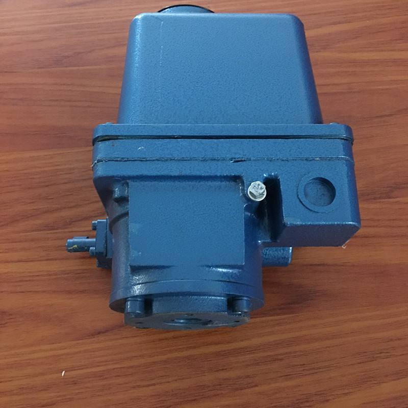
LQ40-1 Valve Electric Device
Application of LQ40-1 Valve Electric Device
LQ40-1 valve electric device is suitable for small and medium-sized butterfly valves, ball valves and plug valves to do 90. The rotary valve is similar to the equipment.
The electric device of the valve is used to assemble the electric valve with the valve. It is used to control the opening and closing of the valve. Operators can control valves from a long distance in the control room, or they can operate manually in the field. This product is widely used in water supply and drainage, heating, power station, chemical industry, food, textile, paper making, pharmaceutical, ship, steel, coal and other projects.
Detailed information about LQ valve electric device welcome to inquire: 0514-85553222
II. Structure of LQ40-1 Valve Electric Device
LQ40-1 Valve Electric Device Series Valve Electric Device mainly consists of motor, deceleration mechanism, stroke control mechanism, torque control mechanism, opening indicator mechanism, handwheel and mechanical limit mechanism.
1. Motor: Valve-specific motor, rated operating time is 10 minutes.
2. Deceleration mechanism: A deceleration mechanism is composed of a first-order spur gear pair and a second-order 2K-H planetary gear train.
3. Travel control mechanism: using cam mechanism. The camshaft is synchronized with the output shaft. There are two micro-switches in the open direction and in the open direction, one is the power supply of the control motor, and the other is the indicator light. The two cams above control the full open position of the valve and the two cams below control the full closed position of the valve. When the valve reaches the end of the journey, the cam touches the micro-switch and the motor stops turning. The stroke of the valve can be changed by adjusting the position of the cam relative to the camshaft. The fastening screw on the cam is in a relaxed state when the product leaves the factory.
4. Torque control mechanism: The worm axial channeling mechanism is adopted. The worm shaft is equipped with a butterfly spring, and the worm axial channeling is changed into camshaft rotation through a crank. The deflection angle of the cam is proportional to the output torque. When the output torque reaches the set output torque, the cam touches the micro-switch, which makes the motor stop turning and the accident indicator lights on.
5. Opening Indicator: It is used to indicate the opening degree of the valve on site. The top of the cam pointer shaft in the stroke control mechanism is equipped with a dial. A potentiometer for indicating the opening of the control room is installed on the side of the cam pointer shaft, and a pair of speed-up straight tool wheels are connected between the cam pointer shaft and the potentiometer.
6. Handwheel: Handwheel is installed on the side of the box. This product is hand-operated to fully automatic switching mechanism, no handles for switching.
7. Mechanical Limiting Mechanism: The function of mechanical Limiting Mechanism is to confine the valve switch (butterfly plate, valve ball, etc.) to a certain working range, so that it can not rotate arbitrarily, so as to facilitate the installation of the valve in the pipeline and determine the position of the valve switch in the pipeline. The mechanical limit mechanism is to set adjustable screw in the opening and closing directions. Please note that the mechanical limit mechanism can not be used to control the limit position of valve opening and closing.
.png)